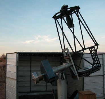
T40CAO - 40cm F/8 Ritchey Chrétien telescope
Published on Tuesday 03 July 2007
This telescope is a 40cm F/8 Ritchey Chrétien telescope. It was built by the italian firm Marcon.
It was delivered to Chile in February, but because of different problems with the customs arrived in San Pedro only in early March.
I installed it as soon as possible on the CAO Paramount. It was a pleasure to remove the counterweights of the old 50cm (35kg) , which is now on a large Astrola mount.
Several problems occurred when trying to use the telescope.
The first one was that the focus system is made in a very strange manner. The Robofocus is installed on the mirror cell, and drives a rod, which goes to the top of the telescope. There another belt and pulley system rotates the shaft of the spider. The system blocking the rotation of the spider's shaft is either loose, in which case the secondary mirror rotates a few degrees (enough so that when one make a focus images the images are shifting about 50 pixels). If it is blocked, then the focus system is blocked and slips. In between it could work, except that during the night, with the temperature change, either one or the other is happening. The Robofocus step size at the focus of the telescope is 0.473 microns ( a bit of an overkill), the backlash is 310 steps. When it works smoothly.
The second thing is that the images were triangular. I dismounted the secondary mirror, or at least tried, because the secondary mirror assembly appears to be blocked. So I dismounted the primary mirror cell. Then quite a shock to see what is called a mirror cell. A cell, with three pads of foam, and 6 radial screws, which were completely blocked on the mirror. I had some problems loosening them, and then remounted the mirror inside the cell, giving it some play, trying to center the mirror using only 3 of the 6 radial screws. I recollimated the telescope, and made images.
So I made this image, once refocalized, but the image size is only 2.8 pixels, or a little bit less than 4". The telescope was pointed in Hercules, at about 40° high above the horizon.
This is the best image obtained in the focalisation series. The fwhm is 2.00 by 2.5 pixels, which is not too good for such a telescope..
Then I pointed near the zenith, near the M22 cluster.
Surprise...
Same focus setting of course than the previous image, and the images were triangular....
Refocussed, I obtained this :
Which I used to make this image in order to finish this night of setting up (5 1min exposure, no filter, log filter applied).
There must be a way to do better.... So more work needed.
I am about to install a JMI focuser at the back end of the telescope, and then will try to see how to make a set of astatic levels in order to support this mirror correctly.
Second step : Improving the focus.
I had a "spare" JMI DFX2 focuser, which I adapted to this telescope. I made also an adaptation for the robofocus motor. So far so good.
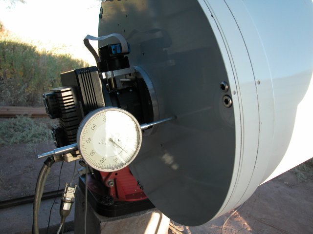
Put a comparator on the camera in order to measure the characteristics. The focus step is now 11.02 microns. The backlash is only 45 microns, so I put 10 steps to be sure in the robofocus backlash setting. Being in direct coupling with the focuser shaft, now the "in" direction of the robofocus moves the camera "out".
There is a slack of about 70 microns between the telescope pointing at the zenith or the telescope pointing at the horizon, but this system will work well enough. It would be fantastic if the software I used were allowing for an altitude correction to the focus correction. The temperature correction I still have to calibrate, but this altitude correction would be really a benefit. Next month I expect to receive a 3 inch JMI focuser for that telescope, and recover my focuser for another telescope I am building now.
Third step : Improving the mirror cell.
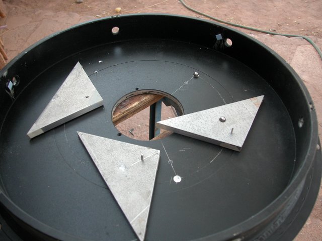
I calculated with Plop the characteristics of a 9 points support. I had very little spare room between the back of the mirror and the cell and had to make a very thin system. I copied from a cell made by Guillaume Blanchard on his 30cm telescope. The interface between the triangles is just a small ball. So I found an old ball bearing, and cut it in half to recover the small metal balls. I made three small conical holes in the cell and in the triangles. I also put three little screws in the triangles which are used as an antirotation system. I had some triangles cut at the correct size. I put tape on the three corners of the triangles in order to have the mirror not touching the aluminium.
The mirror is now slightly higher. I made new radial supports. I calculated they must be at 22.2mm from the top of the edge of the mirror.
The problem is that eventhough I tried very hard to make the holes with the same depth, the mirror resulted slightly tilted in the mirror cell. Measuring from one side of the cell, the highest to lowest point are less than 1mm of difference. I told myself this would not be a problem, I just would have to tilt the mirror cell a little bit. But this is not the case. I tried very hard to get a good collimation and didn't understand what I was getting. If the mirror is tilted in the cell, then the light baffles are not aligned. So ready to dismount and make a last modification, either by adjusting the holes so that the mirror is flat in its cell, or leaving one ball as is, and mounting the other on a screw, which I will adjust in order to get a flat mirror. I spent two parts of night, trying to get a correct collimation and could not. I would move the secondary and the image was still very asymetric. The reason was that the main baffle was cutting part of the images. The first night ended with me quite baffled :), didn't know what was happening. The second night, changing the focus, with a webcam, I saw what was happening. I am also going to make a real size model of the telescope to see how the baffles are calculated, and if they need to be modified. The good thing is that I could check that the images were as bad :) at the zenith or lower on the horizon, not like before. So another problem solved.
I was finally able to dismount the secondary assembly. The mirror is held between its back, with a disk of the same type of foam used in the former primary mirror cell. On the back of the secondary mirror, I found an information which I was needing, which is the fact that the distance between the primary and the secondary should be 820mm, which it is, within a few mm.
So lots of work, getting there, but still need another day of work, a collimation, a pointing model.
Since then I have made some observations. On one occasion, the telescope pointed down, and apparently one of the ball below one of the triangle of the mirror cell changed position, so I had astigmatic images.
Also, the collimation is far from perfect, obtained images of 2.3 pixels wide when the mirror was OK.
So I made more modifications, taking the occasion that the 3" diameter JMI focuser arrived. I installed a piece of aluminium in order to hold the Robofocus motor. I made holes through the tube in order to access the radial screws of the cell. I put the frontal screws in closer contact to the mirror. Also I realized that the contact between the mirror and the triangles of the support were in a way "sticky", meaning that if I unscrewed the radial screws and inclined the mirror, the mirror would not slip, and in fact the balls were slipping before the mirror would slip from the triangles. So dismounted the triangles, and instead of the tape I had put, I drilled some circular holes and put some teflon pads. These teflon pads are 0.5mm above the plane of the triangle. The mirror cell now seems to be healthy.
The last thing I need to do on this telescope is a translation system for the secondary. It is impossible to align a Ritchey Chretien telescope if the secondary is not on the center of the optical axis of the tube. I thought that there was a way around it, tilting first the primary so that the laser arrived on the center of the secondary, then tilting the secondary so that the telescope is aligned. Except that tilting the secondary changes its position in the tube. So I thought that little by little I could arrive to a correct position. But it is really messy, and never converged. Sometimes I would centered optics (as looking from the front of the optical tube, like 3 or 4 times the focal length, but then images taken with the webcam would clearly be out of alignment. More on this. Still getting there, but a lot of work.


